As an important component of the entire power station, the inverter can detect almost all parameters of the power station, from the DC components on top to the grid connected equipment on the bottom. If there is an abnormality, the health status of the supporting equipment in the power station can be checked through the feedback information from the inverter.
- No mains connection
Reason for malfunction:
Indicates that there is no connection to the mains or the AC circuit breaker is disconnected, causing the inverter to not detect the voltage of the mains.
Solution:
- Determine whether the power grid has been cut off. If the power grid has been cut off, wait for the power grid to resume supply.
- If the power supply of the grid is normal, use a multimeter to measure the AC output voltage in the AC voltage range to see if it is normal. First, measure the output port of the inverter and check if there are any problems on the output side of the inverter. If there is no problem, it is a circuit breaker on the external AC side. It is necessary to check the air switch, knife switch, overvoltage and undervoltage protector and other safety switches in sequence for any damage or disconnection.
- AC voltage exceeds the range
Reason for malfunction:
When photovoltaic power generation is connected to the user side power grid, the voltage at the connection point will increase. The higher the internal resistance of the power grid, the greater the appreciation. The closer it is to the transformer, the smaller the line resistance, and the smaller the fluctuation of the power grid. However, the further it is to the end of the power grid, the longer the line, and the greater the voltage fluctuation. Therefore, when the inverter is connected to the power grid far away from the transformer, the working environment of the inverter in the power grid will become very poor. After exceeding the upper limit of the inverter’s working voltage, the inverter will report a fault and stop working. According to the technical specifications for photovoltaic grid connected inverters (NB/T 32004-2018), the requirements for overvoltage/undervoltage protection on the AC output side are as follows: when the AC output voltage of the inverter exceeds the allowable voltage range of the power grid, the inverter is allowed to disconnect from supplying power to the grid, and a warning signal should be issued when it is disconnected. The inverter should be able to start and operate normally when the grid voltage returns to the allowable voltage range.
Solution:
- Try to place the access point of the photovoltaic power station as close as possible to the output end of the transformer to reduce line losses.
- Try to shorten the length of the AC output line of the inverter as much as possible, or use thicker copper core cables to reduce the voltage difference between the inverter and the grid.
- Nowadays, the vast majority of grid connected inverters have AC voltage regulation function. You can contact the manufacturer to widen the AC voltage range to adapt to voltage fluctuations in the power grid.
- If possible, the output voltage of the transformer can be appropriately reduced.
- Low insulation impedance
Reason for malfunction:
The inverter has the function of detecting the insulation impedance on the DC side. When the DC positive and negative pole to ground impedance is detected to be lower than 50k Ω, the inverter will report a “PV insulation impedance too low fault”. In order to prevent the human body from simultaneously contacting the live parts of the panel and the ground, which may cause electric shock hazards, the influencing factors include: leakage of DC components; insulation damage of cables, moisture in the exposed live parts; poor grounding of component supports; and high humidity in weather and power plant environment.
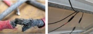
Solution:
Disconnect the AC/DC circuit breaker, use a dedicated MC4 disassembly wrench to remove the positive and negative poles of the DC measurement string to ensure reliable grounding of the component bracket. Use a multimeter with a megohm range, connect the red probe to the positive pole of the string, and connect the black probe to the ground to read the impedance reading of each positive pole to ground. Then connect the red probe to the negative pole of the string, and read the impedance reading of each negative pole to ground. If it is greater than 50k Ω, it is judged that the insulation of the string is reliable. If it is less than or equal to 50k Ω, it is judged that there is a problem with the insulation of the string. The cable condition of the string can be checked separately to see if it is damaged or not in contact. Low insulation impedance, usually due to a short circuit between the positive and negative poles to ground.
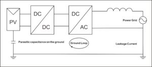
- Excessive leakage current
Reason for malfunction:
The inverter leakage current detection module detected excessive leakage current. To protect personal safety, it stopped working and reported the fault information.
Solution:
- Disconnect the PV input, restart the machine, and observe whether the machine can return to normal.
- Check whether the AC ground wire is connected to the live wire, measure whether the voltage between the ground wire and the live wire is normal, or use a leakage current detector to detect.
- If there is no connection between the ground wire and the live wire during measurement, it is likely due to machine leakage and the manufacturer needs to be contacted for handling.
- DC voltage too high
Reason for malfunction:
Excessive number of series connected components in a single PV string causes the voltage to exceed the PV voltage limit of the inverter
Solution:
Check the parameters of the inverter, determine the input range of the DC voltage, and then measure whether the open circuit voltage of the string is within the allowable range of the inverter. If it exceeds the allowable range, reduce the number of components in series in the string.
Similarly, if the PV voltage is reported to be too low, check if the number of components connected in series is too small, or if the positive and negative poles of the string are reversed, the terminals are loose and have poor contact, or if the string is broken.
- Inverter screen has no display
Reason for malfunction:
- There is no DC input or auxiliary power failure. The inverter LCD is powered by DC, and the component voltage cannot reach the inverter starting voltage.
- Connect the PV input terminal in reverse. The PV terminal has positive and negative poles that correspond to each other and cannot be connected in series with other groups.
- The DC switch is not closed.
- One component is broken, causing other strings to also not work
Solution:
- Use a multimeter to measure the DC input voltage of the inverter in the voltage range. When the voltage is normal, the total voltage is the sum of the voltages of each component.
- If there is no voltage, sequentially check whether the DC switch, wiring terminal, cable joint, components, etc. are normal.
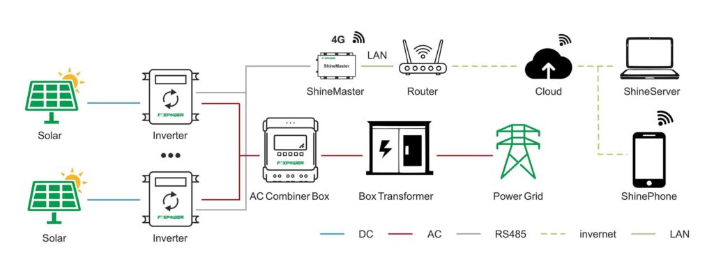
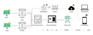
- Monitoring issues
Reason for malfunction:
The collector is not communicating with the inverter; Collector not powered on: installation position signal issue; Internal reasons of the collector
Solution:
- Check if the communication interface between the collector and the inverter is normal, and observe the status of the communication indicator light;
- Check the strength of the local signal, and install an enhanced antenna in areas with weak signals
- Scan the correct collector serial number
- If there is no external condition problem and the collector does not respond to any connection, it can be considered an internal fault of the collector.
Summary
Above, the typical problems of inverters in photovoltaic projects have been analyzed, and some suggestions have been given. The focus is on understanding the causes and solutions of typical problems. At the same time, in the daily maintenance of the power station, perfect safety protection measures and good standardized operation and maintenance are also key to ensuring the revenue of the power station.