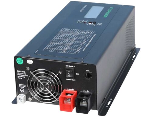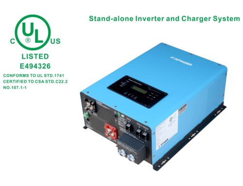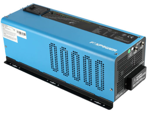
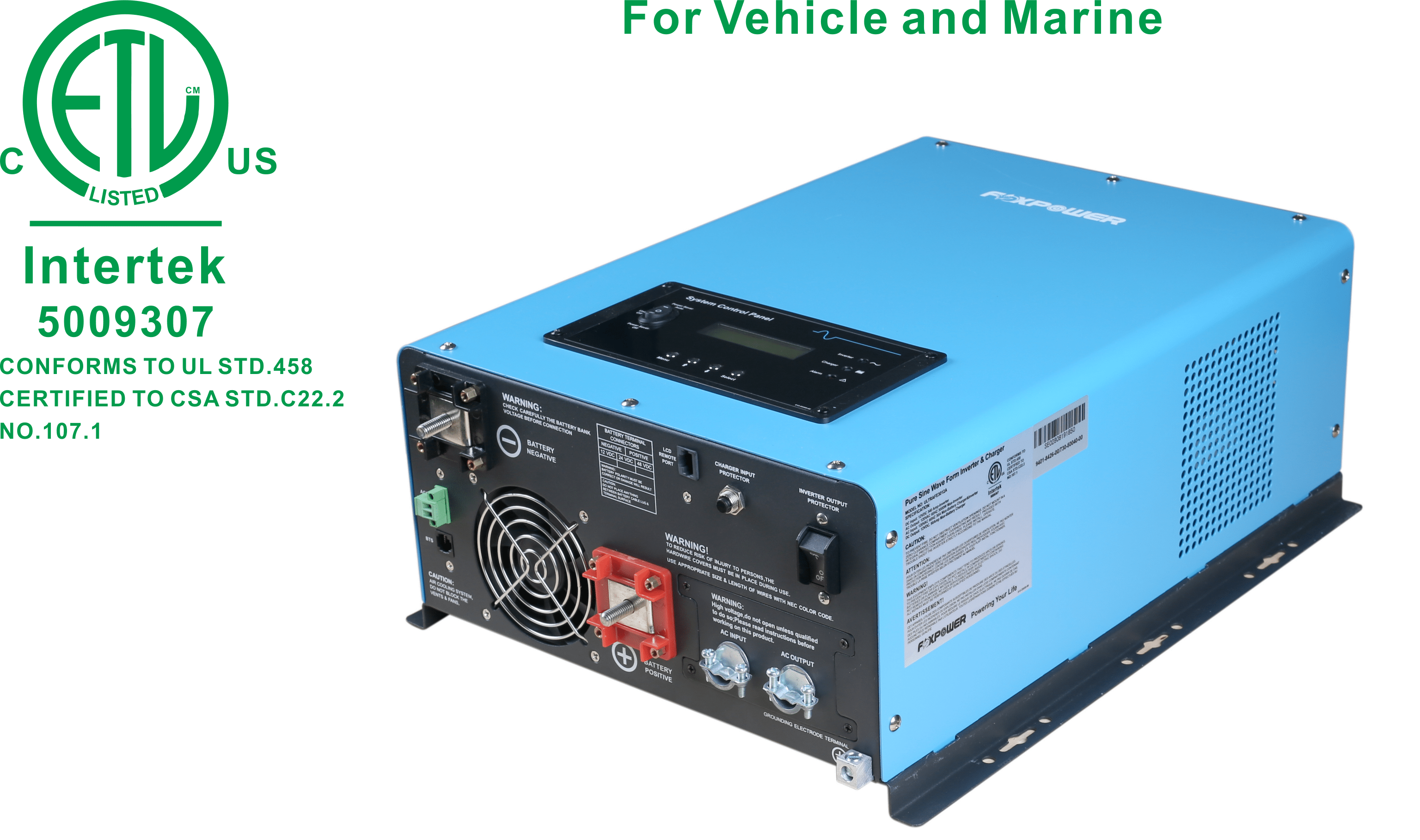
Ultra RV ETL listed conforms to UL458 and CSA C22.2 No.107.1 for Vehicle and Marine
The Ultra RV CSA certificated low-frequency sine wave inverter charger represents a highly sophisticated and advanced inverter charger available in 4500W 24Vdc with 70A, 3600W 24Vdc with 50A charger, 3000W 12Vdc with 90A charger, and 2000W 12Vdc with 50A charger models. The Ultra RV features premium sine wave output with high surge capacity and temperature compensated, power factor corrected, multi-stage charging to meet the power needs of demanding loads including motor loads. All range of Ultra RV inverter chargers is compatible with optional system remote control panel, automatic generator start, and battery temperature sensor. All of the models are approved by UL458, CSA requirements for Vehicle and Marine.
3-stage smart charge
1st Stage – Bulk (Constant Current): This is the initial stage of charging. While Bulk charging, the charger supplies the battery with a controlled constant current. The charger will remain in Bulk charge until the Absorption charge voltage (determined by the battery type selection) is achieved. The software timer will measure the time from AC start until the battery charger reaches 0.3V below the boost voltage, then take this time as T0 and T0*2 = T1.
2nd Stage – Absorption (Constant Voltage): This is the second charging stage and begins after the absorb voltage has been reached. Absorb charging provides the batteries with a constant voltage and reduces the DC charging current in order to maintain the absorb voltage setting. In this period, the inverter will start a T1 timer, the charger will keep the boost voltage in boost CV mode until the T1 timer has run out. Then drop the voltage to the float voltage. The timer has a minimum time of 30 hours and a maximum time of 2 hours.
3rd Stage – Float: The third charging stage occurs at the end of the absorb charging time. While float charging, the charge voltage is reduced to the float charge voltage (determined by the battery type selection). In this stage, the batteries are kept fully charged and ready if need by the inverter. If the AC is reconnected or the battery voltage drops below 12Vdc/24Vdc/48Vdc, the charger will reset the cycle above.
If the charge maintains the floating state for 10 days, the charger will deliberately reset the cycle to protect the battery.
Power Factor Correction Charger (PFC Charger)
The power factor correction (PFC) circuit is designed to draw a sinusoidal current from the AC input line that is exactly in phase with the input voltage. As a result, the converter exhibits a power factor that is very close to unity or one, which is ideal. Foxpower power factor corrected converters are rated at greater than 0.99 power factor, compared to the rating of approximately 0.65 power factor for converters that are not power factor corrected. the improved power factor results in approximately 30% less AC input current required to deliver the same DC charging current.
The benefit of using a PFC charger:
- Improve Charger Performance
- Decreased Operation Cost
- Reduction in Carton Footprint
- Optimum Utilization of Existing
Auto Gen Start
The inverter can be customized to start up a generator when the battery voltage goes low. When the inverter goes to a low battery alarm, it can send a signal to start a generator and turn the generator off after battery charging is finished.
The auto-gen start feature will only work with generators designed to work with this feature. There is an open/close relay that will short circuit the positive and negative cable from a generator. The input DC voltage can vary, but the max current the relay can carry is 16Amp.
Battery Temperature Sensing
Applying the proper charge voltage is critical for achieving optimum battery performance and longevity. The ideal charge voltage required by batteries changes with battery temperature.
The battery temperature sensor allows the charge controller to continuously adjust charge voltage based on the actual battery temperature.
Temperature compensation of charge voltage assures that the battery receives the proper charge voltage as battery temperature varies.
Foxpower recommends that you install battery temperature sensors on all banks to protect your batteries and to provide optimal charging for each bank.
Specifications
Inverter Output specifications
- Output waveform: pure sine wave
- Nominal efficiency: >88% (peak)
- Line mode efficiency: >95%
- Power factor: 0.9-1.0
- Nominal output voltage (RMS): 110-115-120Vac
- Output voltage regulation: ±10% RMS
- Output frequency: 60Hz±0.3Hz
- Short circuit protection: Yes, current limit function (fault after 1 sec)
- THD: <3%
- DC input specifications
- Nominal input voltage: 12vdc (*2 for 24vdc)
- Minimum start voltage: 10.0vdc
- Low battery alarm: 10.5vdc/11.0vdc
- Low battery trip: 10.0vdc/10.5vdc
- High voltage alarm&fault: 16.0vdc
- High DC input recovery: 15.5vdc
- Low battery voltage recovery: 13.0vdc
- Idle consumption search mode:
- Charger specifications
- Input voltage range: 90-135Vac (wide); 100-135Vac (narrow)
- Output voltage: depends on battery type
- Overcharge protection shutdown: 15.7Vdc for 12Vdc (*2 for 24Vdc)
Bypass & protection specifications
- Input voltage waveform: sine wave (grid or generator)
- Nominal voltage: 120Vac
- Low voltage trip: 80/90Vac±4%
- Low voltage re-engage: 90/100Vac±4%
- High voltage trip: 140Vac±4%
- High voltage re-engage: 135Vac±4%
- Max input AC voltage: 150Vac
- Nominal input frequency: 50Hz or 60Hz (auto-detect)
- Low-frequency trip: 47±0.3Hz for 50Hz, 57±0.3Hz for 60Hz
- Low frequency re-engage: 48±0.3Hz for 50Hz, 58±0.3Hz for 60Hz
- High-frequency trip: 55±0.3Hz for 50Hz, 65±0.3Hz for 60Hz
- High frequency re-engage: 54±0.3Hz for 50Hz, 64±0.3Hz for 60Hz
- Output short circuit protection: circuit breaker
- Max bypass current: 30A&40A
- Warranty: 2 years
- Display: LCDs
| Electrical Specifications - Inverter | ULTRAFE2012A | ULTRAFE3012A | ULTRAFE3624A | ULTRAFE4524A |
|---|---|---|---|---|
| Coninuous output power | 2000W | 3000W | 3600W | 4500W |
| Surge Rating (20s) | 6000W | 9000W | 10800W | 13500W |
| Capable of starting electric motor | 2HP | 3HP | 3HP | 4HP |
| Output waveform | Pure sine wave/same as input(bypass mode) | |||
| Nominal efficieny | >88% (peak) | |||
| Line mode efficiency | >95% | |||
| Power factor | 0.9-1.0 | |||
| Nominal output voltage | 100Vac-110Vac-120Vac | |||
| Output voltage regulation | ±10% RMS | |||
| Output frequency | 50/60Hz±0.3Hz | |||
| Power consumption- invertering (no load) | 3.5Adc | 4.0Adc | 3.0Adc | 3.5Adc |
| Power consumption- searching mode | <1.4Adc | <1.6Adc | <1.05Adc | <1.05Adc |
| Transfer time | 10ms (max) | |||
| Total harmonic distortion (THD) | <3% | |||
| Electrical Specifications - Charger | ULTRAFE2012A | ULTRAFE3012A | ULTRAFE3624A | ULTRAFE4524A |
| Input voltage range | Narrow: 100-135Vac; Wide: 90-135Vac | |||
| Input frequency range | Narrow:47-55±0.3Hz for 50Hz, 57-65±0.3Hz for 60Hz | |||
| Input frequency range | Wide: 43±0.3Hz plus for 50Hz/60Hz | |||
| Max charge current | 50A | 90A | 50A | 70A |
| Charger efficiency | 0.8 | 0.8 | 0.8 | 0.8 |
| Over charge current shutdown | 15.7V | 15.7V | 31.4V | 31.4V |
| Output voltage | Depends on battery type *for 12V (*2 for 24V) | |||
| Battery Type | *Absortion mode (Vdc) | *Float mode (Vdc) | ||
| Gel U.S.A | 14 | 13.7 | ||
| A.G.M 1 | 14.1 | 13.4 | ||
| A.G.M 2 | 14.6 | 13.7 | ||
| Sealed lead acid | 14.4 | 13.6 | ||
| Gel Euro | 14.4 | 13.8 | ||
| Open lead acid | 14.8 | 13.3 | ||
| Calcium | 15.1 | 13.6 | ||
| De-sulphation | 15.5 for 4hrs (12v model) | 31 for 4hrs (24v model) | ||
| Electrical Specifications - DC Input | ULTRAFE2012A | ULTRAFE3012A | ULTRAFE3624A | ULTRAFE4524A |
| Nominal input voltage | 12.0Vdc | 12.0Vdc | 24.0Vdc | 24.0Vdc |
| Minimum start voltage | 10.5/11.0/11.5/12.5Vdc | 21.0/22.0/23.0/25.0Vdc | ||
| Low battery alarm | 10.5/11.0/11.5/12.5Vdc | 21.0/22.0/23.0/25.0Vdc | ||
| Low battery trip | 10.0/10.5/11.0/12.0Vdc | 20.0/21.0/22.0/24.0Vdc | ||
| High voltage alarm & fault | 16.0Vdc | 16.0Vdc | 32.0Vdc | 32.0Vdc |
| High DC input recovery | 15.5Vdc | 15.5Vdc | 31.0Vdc | 31.0Vdc |
| Low battery voltage recovery | 13.0Vdc | 13.0Vdc | 26.0Vdc | 26.0Vdc |
| Electrical Specifications - Bypass & protection | ULTRAFE2012A | ULTRAFE3012A | ULTRAFE3624A | ULTRAFE4524A |
| Input voltage waveform | Sine wave (grid or generator) | |||
| Nominal voltage | 120Vac | |||
| Low voltage trip (Wide/Narrow) | 80V/90V±4% | |||
| Low voltage re-engage (Wide/Narrow) | 90V/100V±4% | |||
| High voltage trip | 140V±4% | |||
| High voltage re-engage | 135V±4% | |||
| Max AC input voltage | 150Vac | |||
| Nominal input frequency | 50Hz or 60Hz (auto detect) | |||
| Low frequency trip | Narrow: 47±0.3Hz for 50Hz, 57±0.3Hz for 60Hz | |||
| Low frequency trip | Wide: 40±0.3Hz for 50Hz/60Hz | |||
| Low frequency re-engage | Narrow: 48±0.3Hz for 50Hz, 58±0.3Hz for 60Hz | |||
| Low frequency re-engage | Wide: 45±0.3Hz for 50Hz/60Hz | |||
| High frequency trip | Narrow: 55±0.3Hz for 50Hz, 65±0.3Hz for 60Hz | |||
| High frequency trip | Wide: 70±0.3Hz for 50Hz/60Hz | |||
| High frequency re-engage | Narrow: 54±0.3Hz for 50Hz, 64±0.3Hz for 60Hz | |||
| High frequency re-engage | Wide: 65±0.3Hz for 50Hz/60Hz | |||
| Output short circuit protection | Breaker | Breaker | Breaker | Breaker |
| Electrical Specifications - General | ULTRAFE2012A | ULTRAFE3012A | ULTRAFE3624A | ULTRAFE4524A |
| Mounting method | Versatile mounting | |||
| Display | LCD+LED status display | |||
| Warranty | 2 Years | 2 Years | 2 Years | 2 Years |
| Automatic Generator Start (AGS) | Yes | Yes | Yes | Yes |
| Battery termperature sensor | Option | Option | Option | Option |
| Remote control panel | Option | Option | Option | Option |
| Regulatory and environment compliance | ETL & c-ETL certificated to CSA 107.1, UL458 | |||
| Inverter dimensions (L*W*H) | 460mm*328mm*178mm | |||
| Inverter weight (kg) | 23 | 26.5 | 25.5 | 31.5 |
| Shipping dimensions (L*W*H) | 580mm*450mm*285mm | |||
| Shipping weight (kg) | 28 | 31.5 | 30.5 | 36.5 |
| Working temperature | 0-40℃ | 0-40℃ | 0-40℃ | 0-40℃ |
| Storage temperature | 0-70℃ | 0-70℃ | 0-70℃ | 0-70℃ |
your content will go here